Mac Keyboard Interface
This is a project to interface with the Mac 128k/512k/Plus keyboard port. This will kind of be an ongoing work in progress for a while, updates will be posted here.
Update September 19 2013
Update August 19 2013
Update July 22 2013
Hardware
This project is using the STM32F0DISCOVERY board, which is $8 from digikey and comes with a little perfboard. With any luck, whatever comes out of this project will be cheap, and not require a separate PCB, making it fairly accessible.
The stm32f0discovery is a 3.3V device with 5V tolerant GPIOs. The mac keyboard interface is 5V, so I need a level converter. I'm currently using this cheap converter from adafruit. It comes on a little PCB with headers and can be attached to the stm32f0discovery's perfboard easily. There was some concern about whether this could handle the speed of the keyboard protocol, but it appears to not be a problem at all.
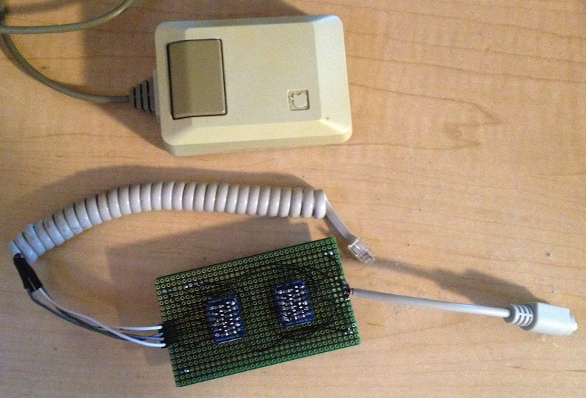
The Mac keyboard plug is an RJ11 4P4C connector, meaning it's a little telephone jack with only 4 positions (and all 4 are connected). Most telephone cords have RJ11 6P4C connectors (6 position, 4 conductor) which means they are wider than will fit in the keyboard plug. Typically those coiled cables that connect old handsets to their base phone are 4P4C connectors and will work for making a cable.
Pinout:
When holding the RJ11 plug away from you, with the connector tab on the bottom, pin 1 is on the left.
Pin 1: Ground
Pin 2: Clock
Pin 3: Data
Pin 4: +5V
Mac Protocol:
This has been the reference I've been working from for the protocol.The commands currently supported are:
Model Number (0x16) which is returning 0x03 at the moment, indicating a keyboard is present, with model number 1, with no additional (keypad) devices present.
Inquiry (0x10) currently responds with just null (0x7B).
The keyboard has exclusive control over the clock, and the data line is bidirectional, although the computer can be thought of as the "master". The keyboard cannot initiate communication with the computer.
At idle, both clock and data are held high. When the computer wants to talk, it pulls the data line low, and the keyboard starts clocking. However, the keyboard cannot immediately start clocking, it needs to wait some period of time (I am currently waiting about 180us) before starting the clock otherwise the computer will miss the first clock cycle and only 7 bits will be transferred (shifted left too).
The computer will first send the Model Number request to the keyboard. After the keyboard responds, the computer will then send an Inquiry command. The keyboard can then immediately respond with any keycode, or if no key has been pressed, wait up to 250ms and respond with a null key code (0x7B). If the computer has not received a response within 500ms, it will reissue the Model Number request. It is my observation that the computer will immediately send another Inquiry command following the keyboard's response. Because of this, the keyboard is responsible for rate limiting the computer's polling by delaying responses.
Here is the logic analyzer's view of the Model Number command and response:
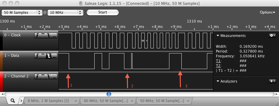
At Step 1, the Model Number command is issued (0x16), Step 2 is the end of the command and beginning of the response (0x03), and Step 3 is the end of the response.
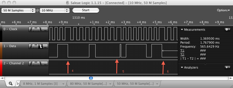
At Step 4, the Inquiry command is issued (0x10), Step 3 is the end of the Inquiry command and beginning of the response (0x7B), Step 6 is the end of the response.
I'm currently using the timings documented in the above reference. When the computer is talking to the keyboard, the clock is low for ~180us, high for ~220us. When the keyboard is talking to the computer, the clock is low for 160us, high for 170us. When the keyboard sends data to the computer, I am currently toggling the data line at the falling edge (beginning) of the clock cycle, and holding it through the entire cycle. When reading data from the computer, I am sampling the data line in the middle of the clock cycle. So far this appears reliable.
PS2 Protocol
This was an invaluable asset when implementing the PS2 side of things. Pretty much everything needed is there. My implementation uses the same level converter above, and implements the PS2 side of the protocol by just polling the data and clock lines. I'm mapping the PS2 Scan Code Set 2 to the macintosh scan codes defined in Inside Macintosh Volume III. I do support both keyboard to host and host to keyboard. It does support toggling the capslock LED.
Building it
Building one of these is pretty simple. The stm32f0discovery comes with a perfboard, and I used two level converters, plus the mac keyboard cable and ps2 keyboard cable, and some wires:Parts:
- One stm32f0discovery kit.
- Two level converters
- One Mac keyboard cable, similar to this telephone handset cord with RJ11 4P4C connectors. I have not used that particular one but I used a similar one.
- One PS2 female jack. I cut up a PS2 to AT keyboard converter cable.
- Some wire to connect everything up.
The level converters arrive with the headers not soldered to the board. Solder the headers on the level converter boards.
I cut the handset cord in half (now I have two!), and identified the wires inside. There should be four. Solder them into the holes on one end of the perf board included with the stm32f0discovery, ideally in pin order (described above) to keep things easy.
Solder one of the level converters to the perf board. When orienting them, orient the "HV" (High Voltage) side of the level converter toward the keyboard cable. After soldering on the level converter, the level converter PCB will be oriented away from the stm32f0discovery PCB (ultimately opposite the "top" of the stm32f0discovery).
Solder wire between the Mac keyboard cable and the level converter, all wires on the "HV" side of the converter:
Pin 1: ground -> HV side GND
Pin 2: Clock -> B1
Pin 3: Data -> B2
Pin 4: +5V -> HV
Solder the PS2 connector to the perf board, again keeping the wires in order is helpful. Looking at the end of the female PS2 connector, the pinout is:
    6 | 5
   4     3
    2   1
Pin 1: dataPin 3: ground
Pin 4: +5V
Pin 5: clock
Solder the other level converter to the perf board. Keeping the "HV" side near the PS2 connector will help.
Connect the PS2 connector to the level converter: Pin 1: data -> B2
Pin 3: ground -> GND
Pin 4: +5V -> HV
Pin 5: clock -> B1
Also connect ground on both sides of the level converter together. The stm32f0discovery will be powering the keyboard, so the grounds need to be the same.
Solder the perfboard to the bottom side (the side with the longer pins) on the stm32f0discovery. Put the side of the perfboard with the level converters "down", facing away from the stm32f0discovery. I found it helpful to solder the first two pins of every corner. Two pins instead of one because we'll be needing to solder wires to the corner pins (they're ground, +5V and +3V) and we don't want the perfboard to move around when soldering those.
Connect the ground and power pins on the LV sides of the level converters:
Connect the LV side ground on both to GND pins on the stm32f0discovery (they're labeled).
Connect the LV pins to +3V on the stm32f0discovery. It's labeled, and should be the top left pin.
Connect +5V on the stm32f0discovery to the HV pin on the PS2's level converter. This will power the keyboard.
Connect the PS2's level converter's pins to the stm32f0discovery:
A1 (clock) -> PC.6 on the stm32f0discovery
A2 (data) -> PC.7 on the stm32f0discovery
Connect the mac keyboard side's level convert pins to the stm32f0discovery:
A1 (clock) -> PC.8 on the stm32f0discovery
A2 (data) -> PC.9 on the stm32f0discovery
That should be it for assembling it.
Update 7/22/2013
PCBs arrived: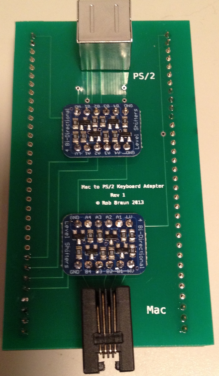
I've also updated the code to handle some of the keypad keycodes. The keypad appears to have evolved between the initial release of the keypad, and the release of the Plus extended keyboard. This has the arrow keys working, the numbers, enter, '.' and '-'. There's not really a good mapping for the "Clear" key on the keypad. I guess a PS2 numlock key could suffice, since it's in the same location?
Update 8/19/2013
New revision! This time without the level converters, and with mouse support! I found the level converters were not necessary, and were a large part of the price of the board.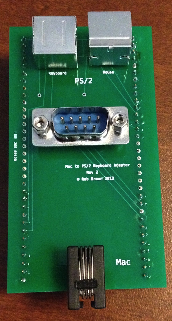
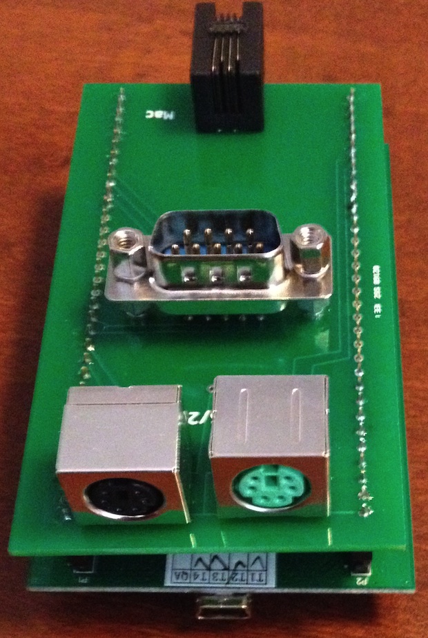
The Mac mouse uses a rotary quadrature for the mouse movement. It allows the mouse to be exceptionally simple, but can stump emulating it. The approach I used was to take advantage of one of the signals being an interrupt. Essentially, there are 2 signals for each axis. One signal for each axis is used to generate an interrupt on the rising and falling edge. The direction is determined by whether it is a rising or falling edge, and the state of the other signal. So rather than trying to generate 2 pulses out of phase with each other, then worrying about determining direction, I simply make sure the non-interrupt line is in the state I want it to be in prior to transitioning the signal used as the interrupt.
Update 9/19/2013
This version now includes ADB!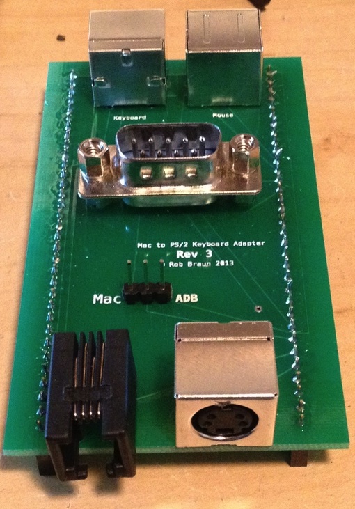
The ADB and pre-ADB both receive all the PS2 events, so it's possible to drive two machines with one keyboard/mouse. I put a jumper on there to select between ADB and pre-ADB, but ended up not using it. Outputting to both simultaneously works out fine, and if one interface isn't used, oh well. Here is a video of it controlling a Plus and an SE simultaneously:
Code
The code is checked into my svn repository hereThe current version I'm using is: mackbd-0.4.tar.bz2 Updated August 19 2013